"Vintage" radio fix
This little unit was found whilst dumpster diving
Perfect for the cottage
The model is AEW510A,
it seems
The problem
Started suspecting something was the reason why it was located in the
dumpster.
It did not in fact start up when power button was pressed.
Time for a random repair.
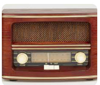
Teardown
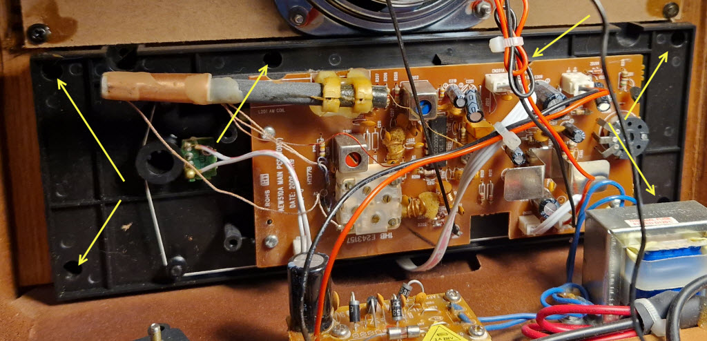
Rear of the unit had some wood screws holding it in place, easily opened.
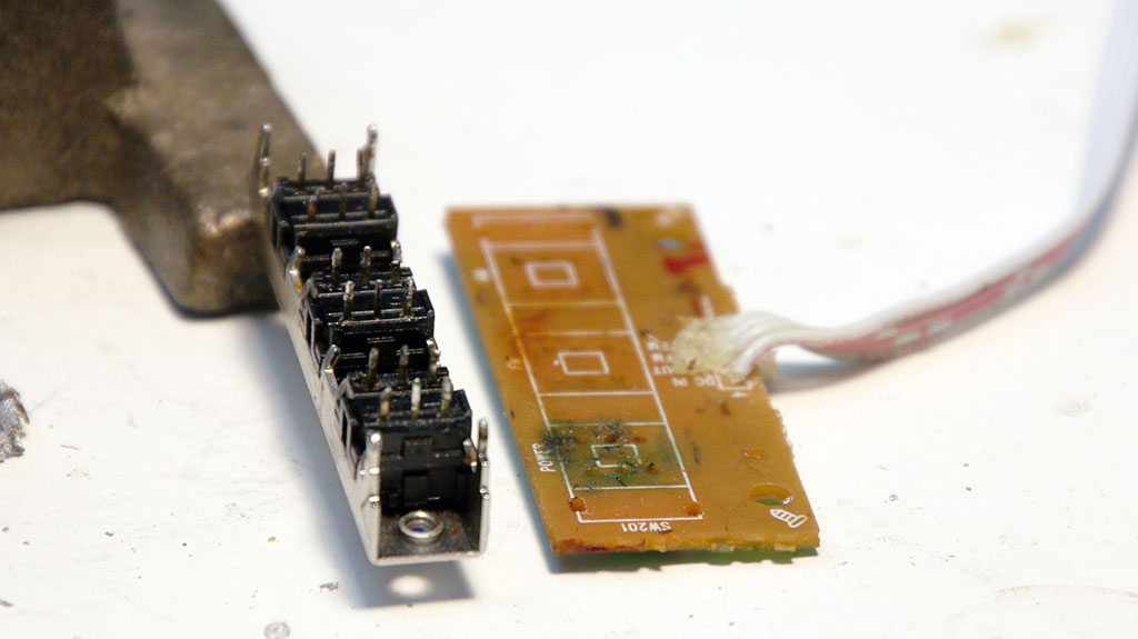
Behind the back cover it is rather simple, there is one power board, one radio PCB, speaker, transformer and out of view is a PCB with the switches.
Plenty of space.
Some measurements
Some quick of checkpoints were tested.
Connected a multimeter to the output of the power board.
There is
no voltage controller nor some fansy regulation other then rectifier with a capacitor, voltage was near 12V, no problem there.
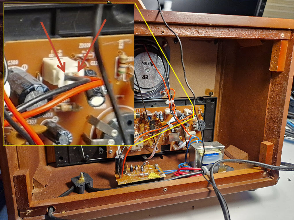
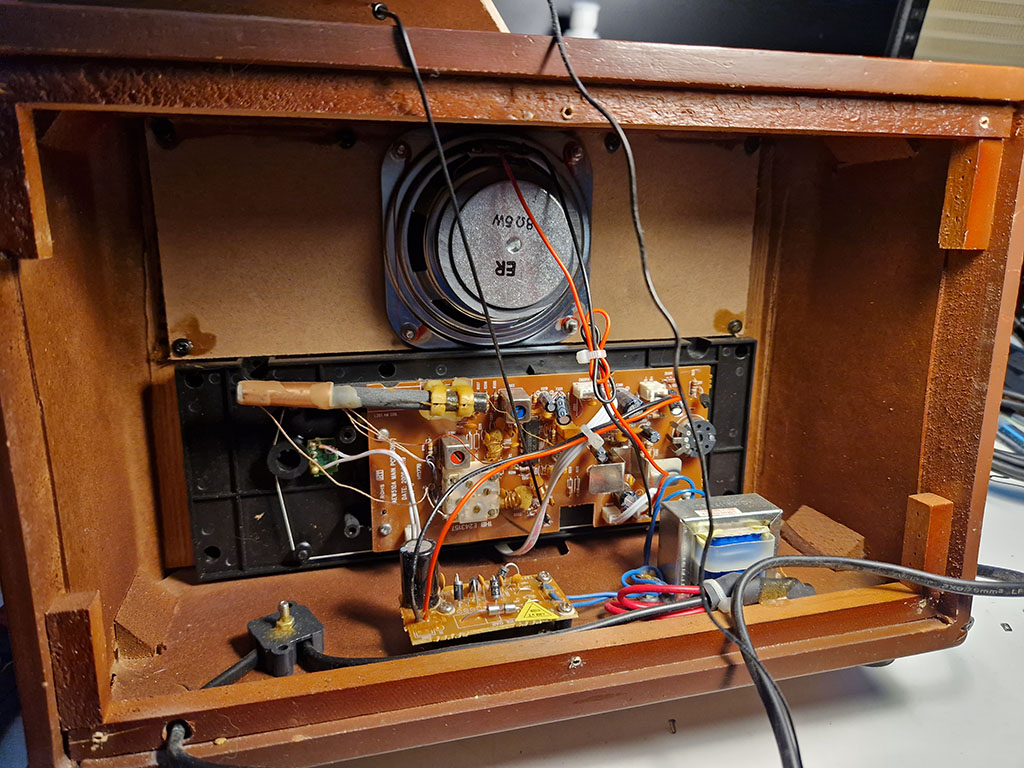
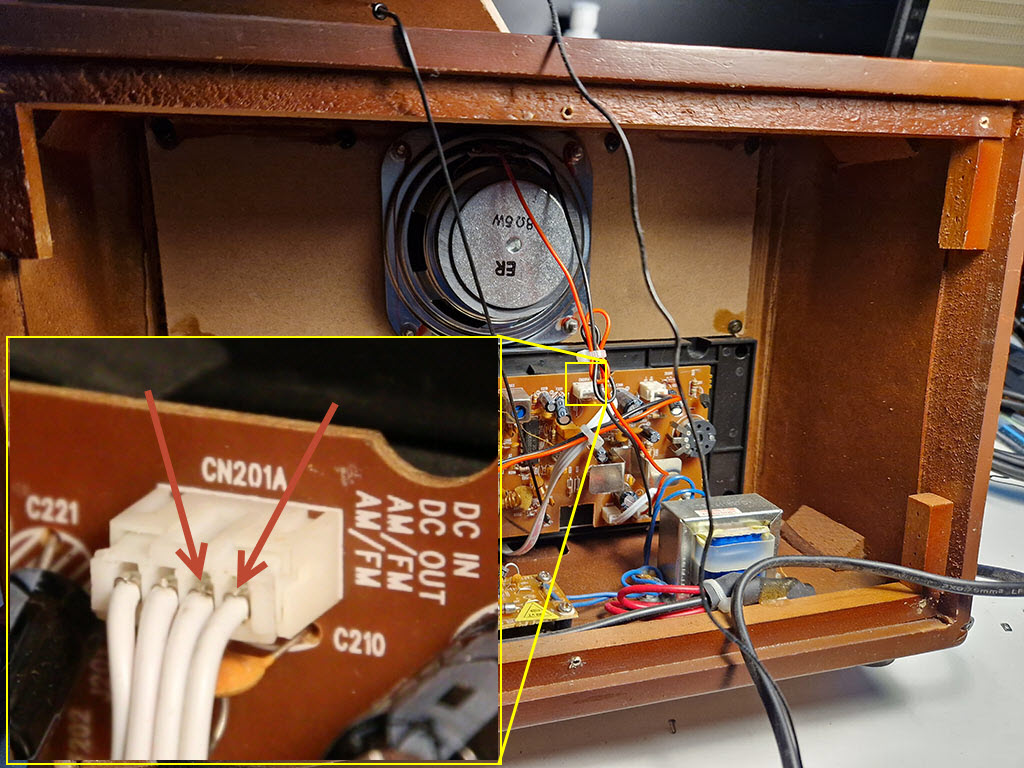
Input voltage to radio board.
Next point is to see that the board gets the voltage past the power switch.
First I disconnected power source, then removed this white connector
when probing the points while changing state of the power switch in the front I could not measure a continuity.
SW measure point.
This could be a really easy fix, replacing the functionality of the switch
with a metallic bypass I might able to start it.
Caution to the wind, lets test the theory:
It's Alive!
That popping sound when the unit powers on hints at something that
poorly chosen switches just aren't built for.
Verifying that there actually is capacitor discharge that makes the sound is tested next.
Sparks flying.
Yes, it arcs pretty bad.
Time to look at the switch PCB
A closer look
Removal of the radio board needs to be done to get to the switch PCB
since the radio channel display is blocking the screws.
Remove these screws.
Latching tactile Switch for power.
Switch PCB is securd by two screws to the base of the radio.
For some reason the engineers thought a DPDT switch is suitable to handle capacitor discharge.
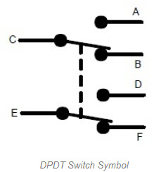
DC 30V 0.1A according to some datasheet.
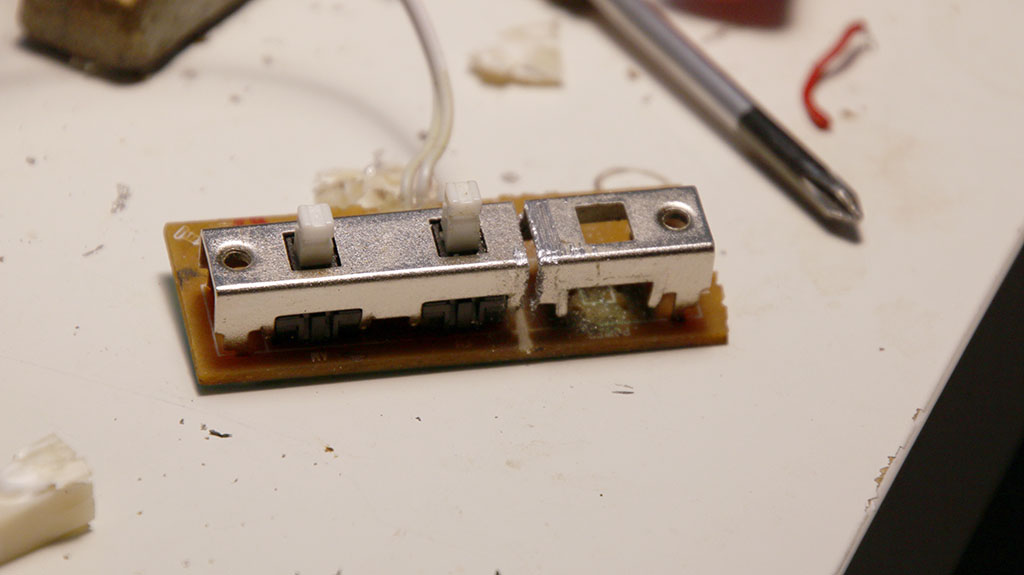
Need to remove the metallic bridge securing the switches.
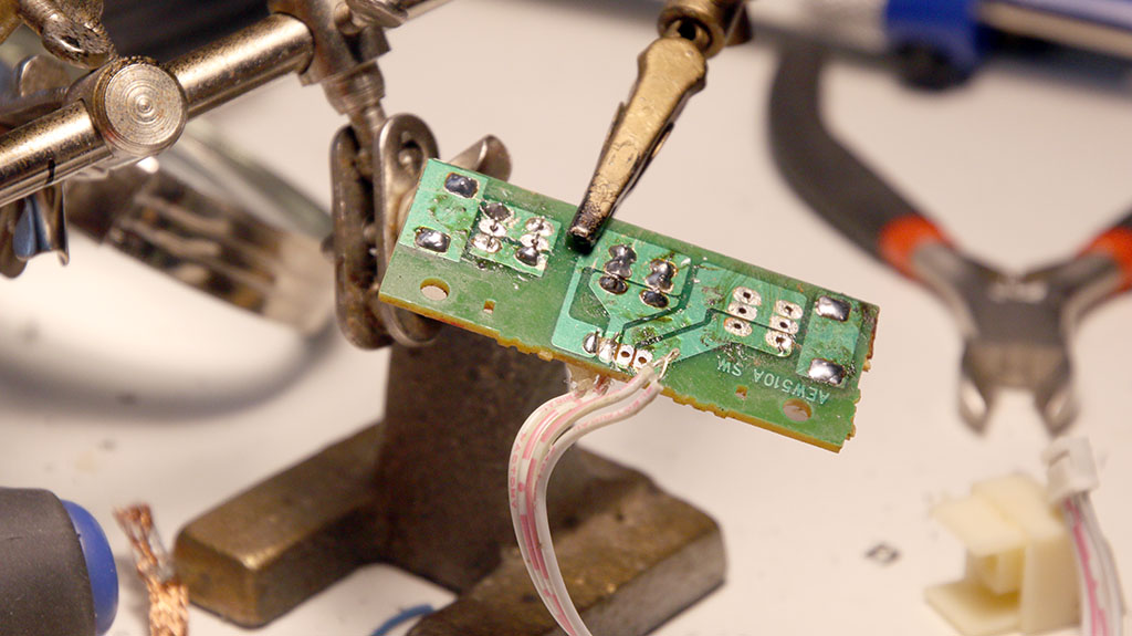
Switch bridge desoldered.
Switch bridge removed.
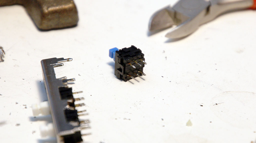
Faulty switch removed from bridge.
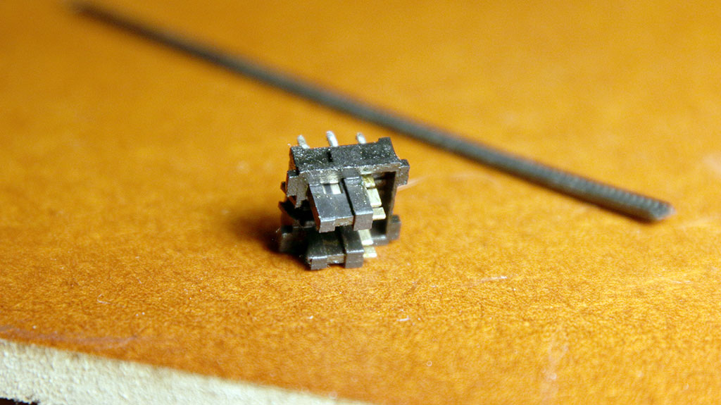
Switch dissasembled.
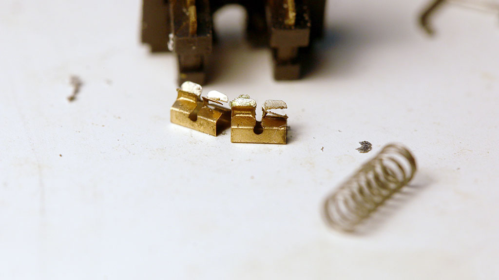
Sliders fried from capacitor discharge.
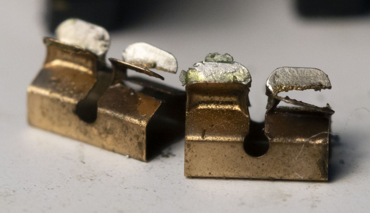
Macro photo of the fried sliders .
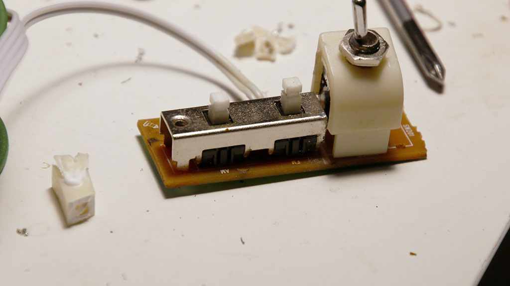
Replacing the switch
Located an old timey flipswitch in some random
assortmentbox.
I could opt for a proper mosfet solution but it would lack the
feel of a
real toggle between on and off.
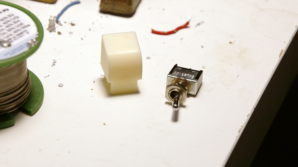
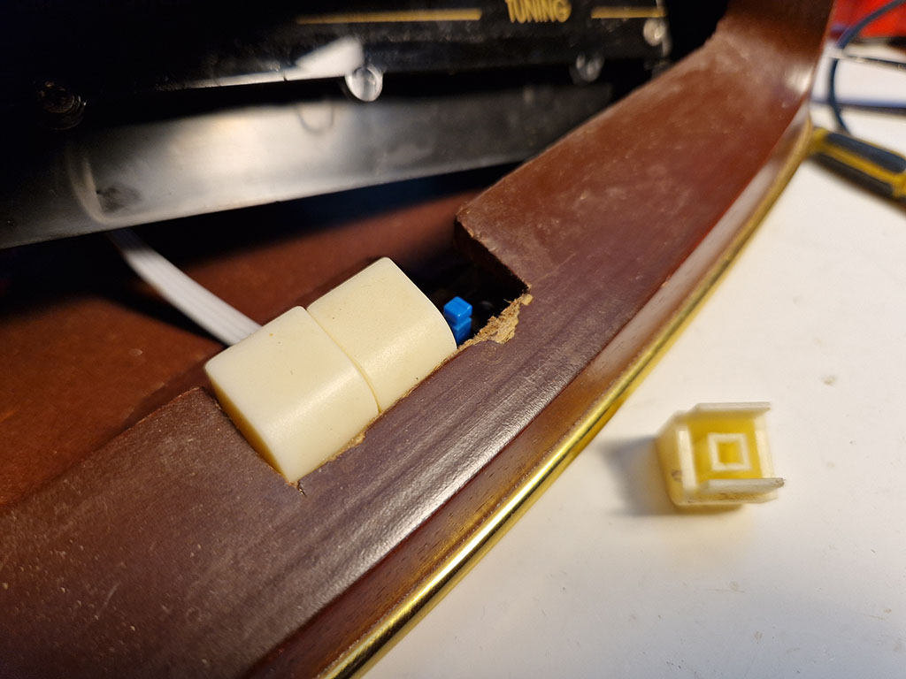
Flipswitch.
Removed the pillar from inside of the old button, drilled
and removed
som material to make room for the new switch.
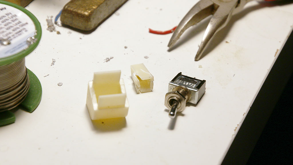
Testfit.
Some cutting is needed for the swich assembly to fit on the PCB.
Cut unncessary metal.
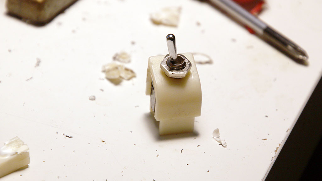
It fits, it sits.
Glue will never hold it place, better to stich it
with metal wire, front and back.
Then glue can be added. (cyanoacrylate).
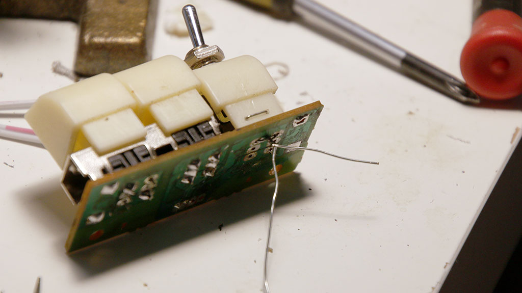
Metal wire from a prototype lead.
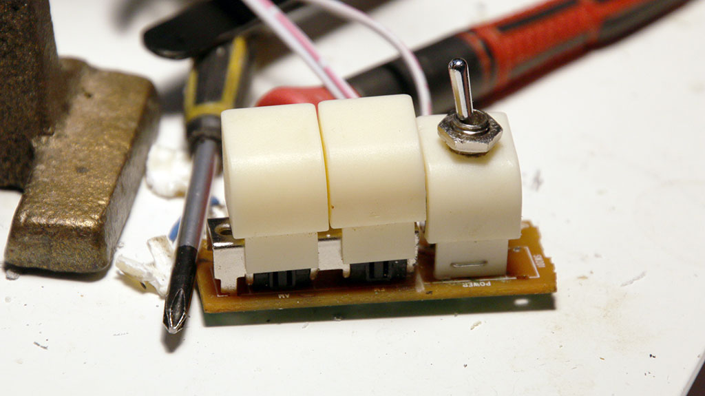
Flipswitch, stitched and glued.
All done, Installation is in reverse, nothing special.
Lets try it out
Power on with new switch.
Final -20230812
Thoughts -20240201
Think I'll make a mod, perhaps add a bluetooth receiver.