DIY electrical bicycle
Gate driver based PWM build
IR2111 gate driver
Gas handle
Voltages
green = Vout
Red 5V
Black = gnd
no throttle = 4.43V
full gas = 1.02V
1.02 / 0.01948 = 52,4 = 0b00110101 => measured to 56 via adc = 0b00111000
4,43 / 0,01948 = 227,4 = 0b11100011
4,3 / 0,01948 = 220 => 210 = 0b11010010 -because small gap with 0 throttle
PWM
0b00111000= 99%
0b11010010 = 0%
translate into" logarithmic" steps
56 -> 210 =154 steps
0 - 99% for pwm is 0-253 binary
PORTD pin 6
output pin for the PWM mode
Brake handle
no brake
4 = 0b0000100
full brake
133 = 0b10000101
=> >125 = 0b1111101
Current sensor
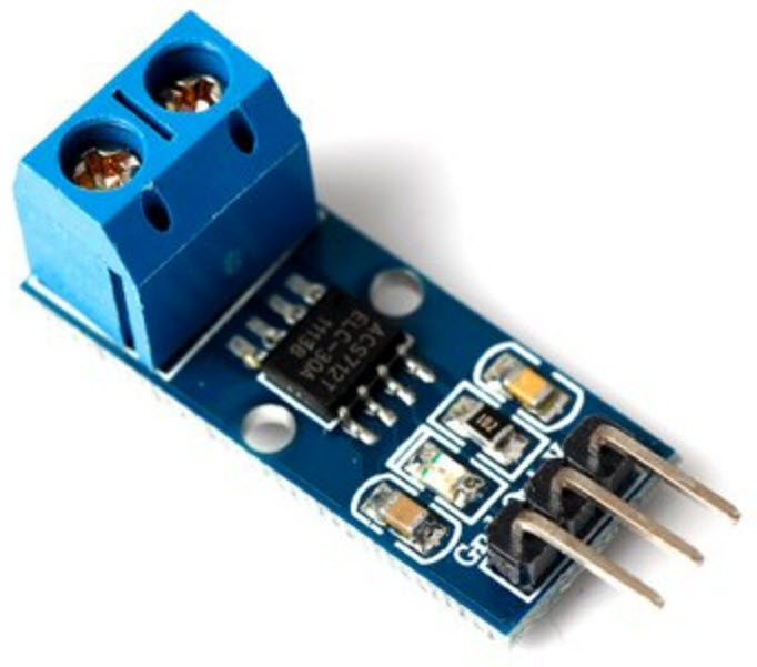

Using the 30A model:
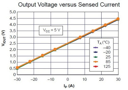
ADC at 19.48mV / step
DC motor built for 250W
simplified:
(4,5-2,5)/0,066 = 30,3A
Battery:
ADC battery voltage via voltage divider and 5.1V zener protection
4,2V is fully charged => ADC value of 215,6=0b11011000
Full
6s -> 4.20V*6 = 25,20V
250W/25,20 = 9,92A => (max current allowed for voltage level)
(x-2,5)/0,066=9,92A
=> x =0,066*9,92A + 2.50 = 3,15 => 3,15/0,01948 =161,95=> 0b10100010 on the ADC
Empty
6s -> 3.6*6 = 21,60V
250W/21,60V = 11,57A => (max current allowed for voltage level)
(x-2,5)/0,066=11,57A
=> x =0,066*11,57 + 2.5 = 3,26 => 3,26/0,01948 =167,55=> 0b10101000 on the ADC
readout is for
battery charge level
100% 4.20 volts
90% 4.15
80% 4.10
70% 4.05
60% 4.00
50% 3.95
40% 3.90
30% 3.85
20% 3.80
10% 3.70
using "pessimistic" scale
in code
// 80% 4.10 * 6 = 24.6V
// 70% 4.05
// 60% 4.00
// 50% 3.95 * 6 = 23,7V
// 40% 3.90
// 30% 3.85 * 6 = 23,1V
Ignition
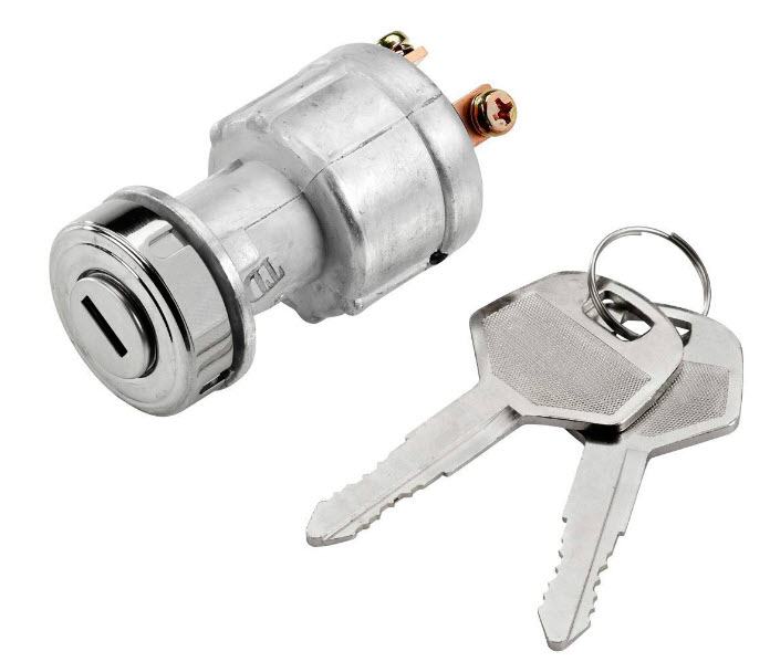
spark supressor 2.2kΩ
25/2200 = 0,01A
battery:
16Ah / 0.01A =1440h = 60days? on the bike
resistor placed between connectors
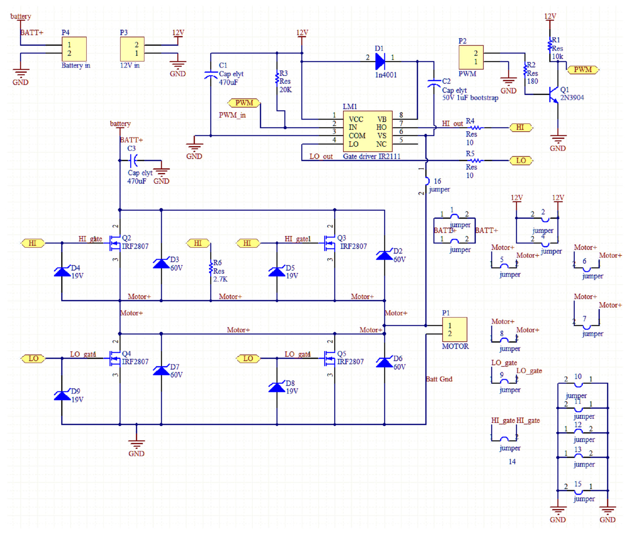
Schematic
Driver board
19V zener as gate protection
60V zener as transient protection
IRF2807 mosfet x4 75V
gate pulldown resistor for high side
IR2111 driver
transistor BC639 for stable PWM pulldown rail to GND
High output and low output via 10 Ω resistors
I/O board
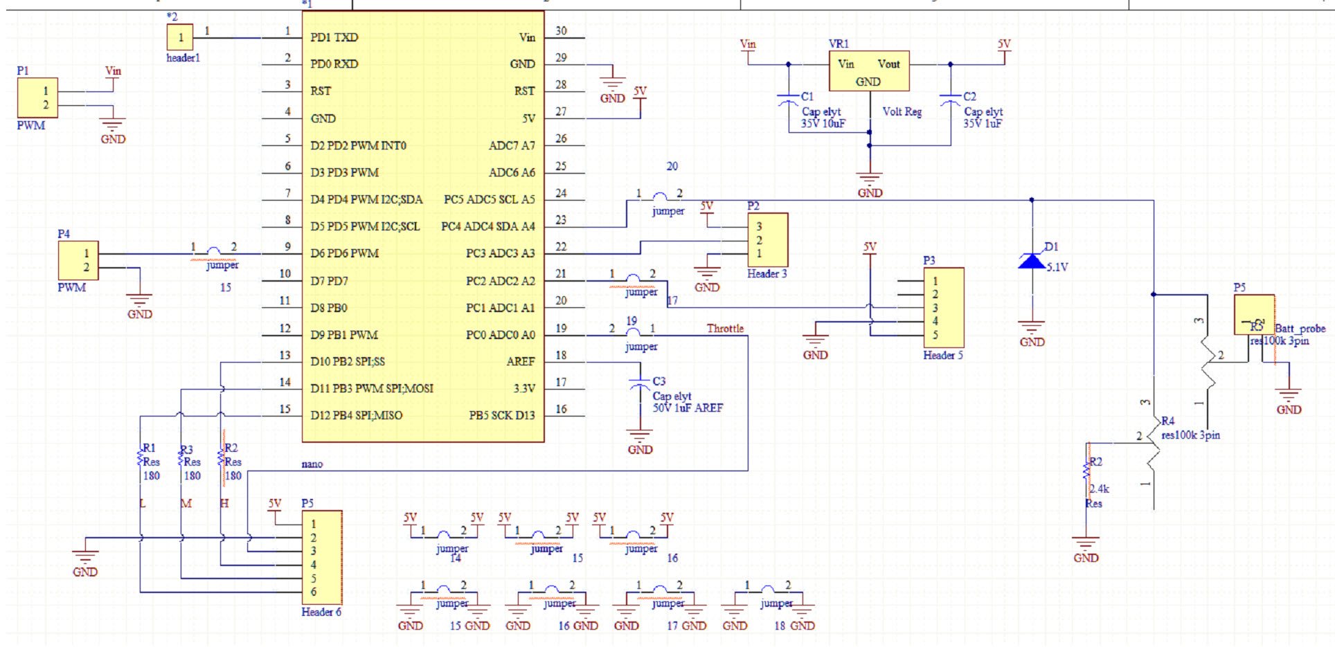
*5.1V zener as input protection for the battery voltage divider
*LM7805 5V LDO as VCC for the arduino(more reliable)
*2x 100kΩ as voltage divider 1:6 with 2.4k short circuit protection
*headers from the original motor controller
Prototype board
each part of the bike tested on prototyping board
step by step testing of each individual component and finally combining them
separate rails for 5V, 12V and battery (6s Lipo)
arduino
gate driver IR2111
Mosfets IRF2807
voltage divider
"gas" handle
brake handle
low medium high LED on handle
Current sensor module ACS712 (20A)
done step by step to verify function
PCB
building on prototype board since it will work well enough
PWM
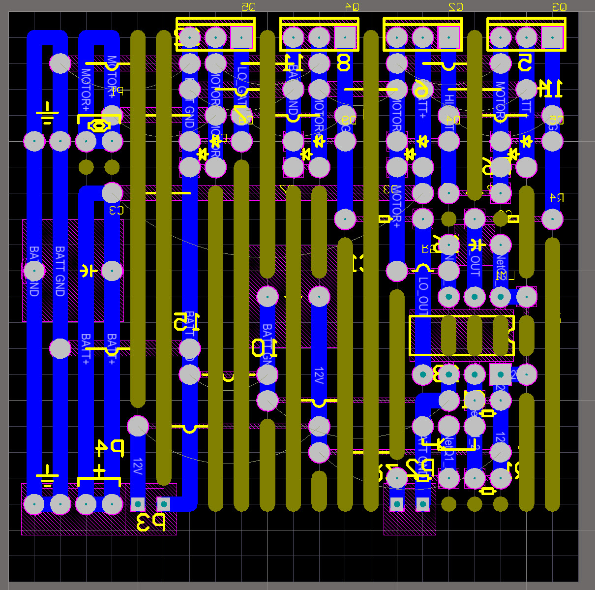
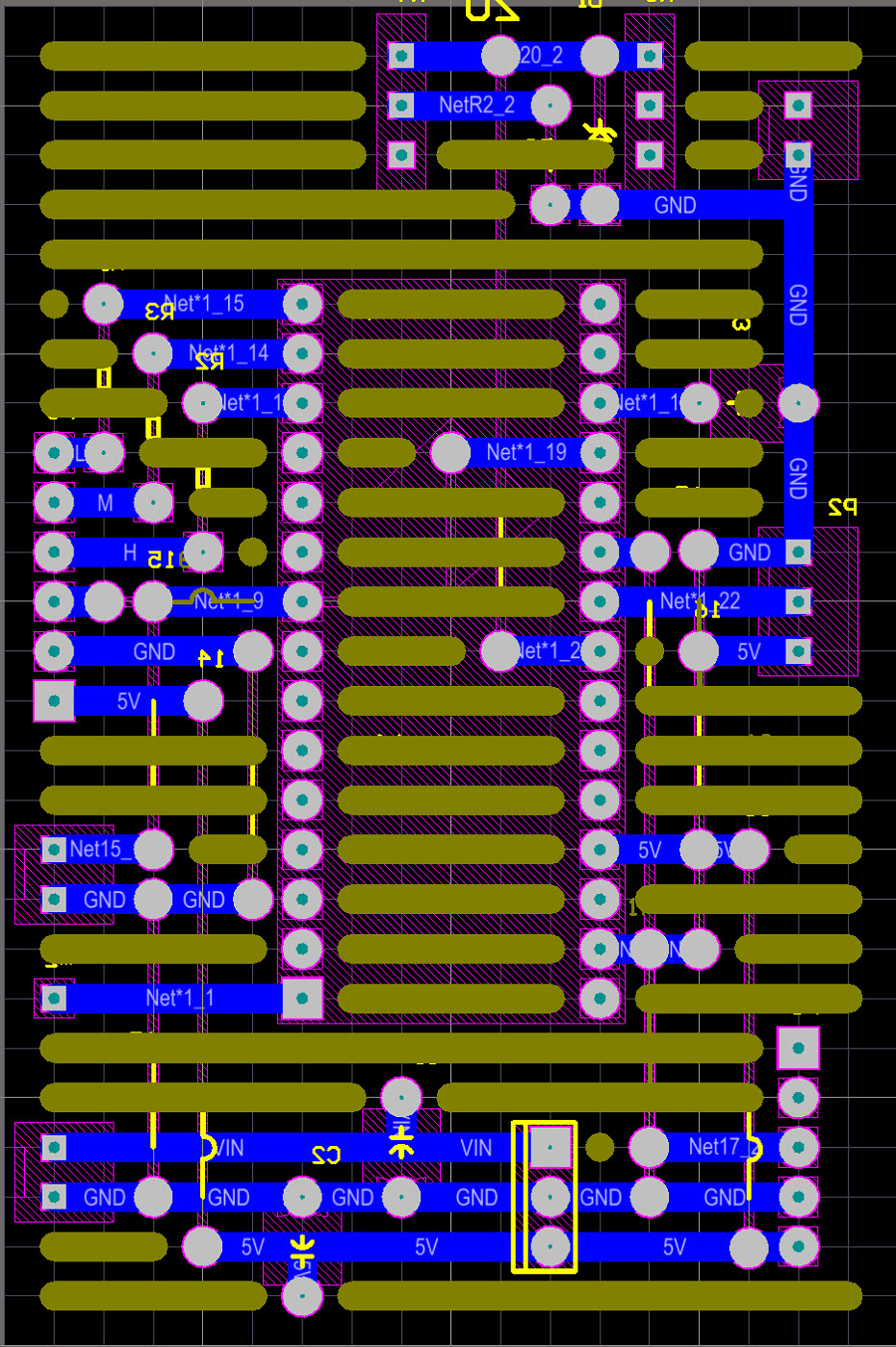
layout
underside, olive colour are tracks to remove or cut away from blue
headers soldered on tracks that needsto be verified in stages
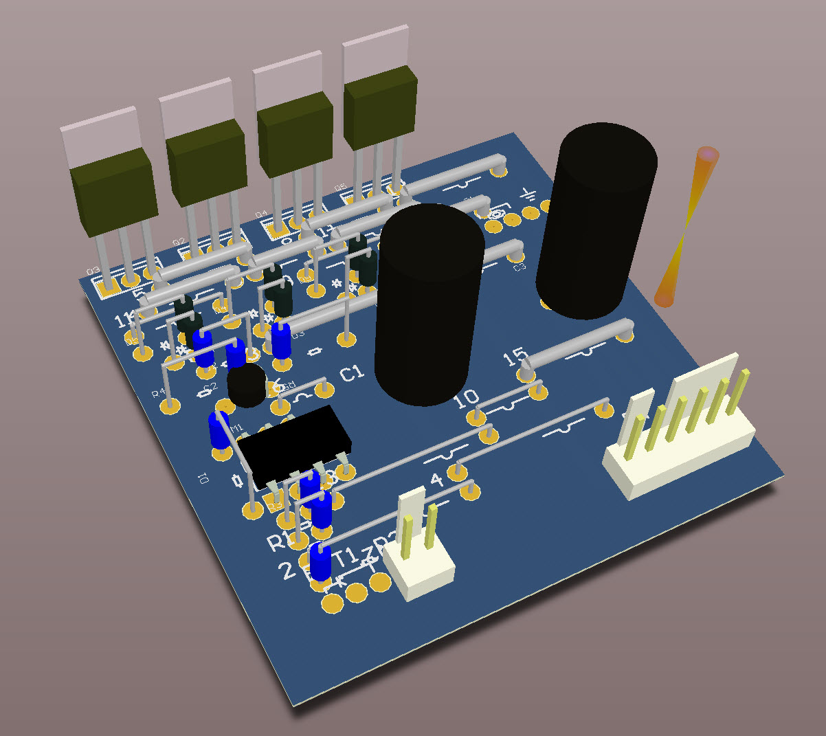
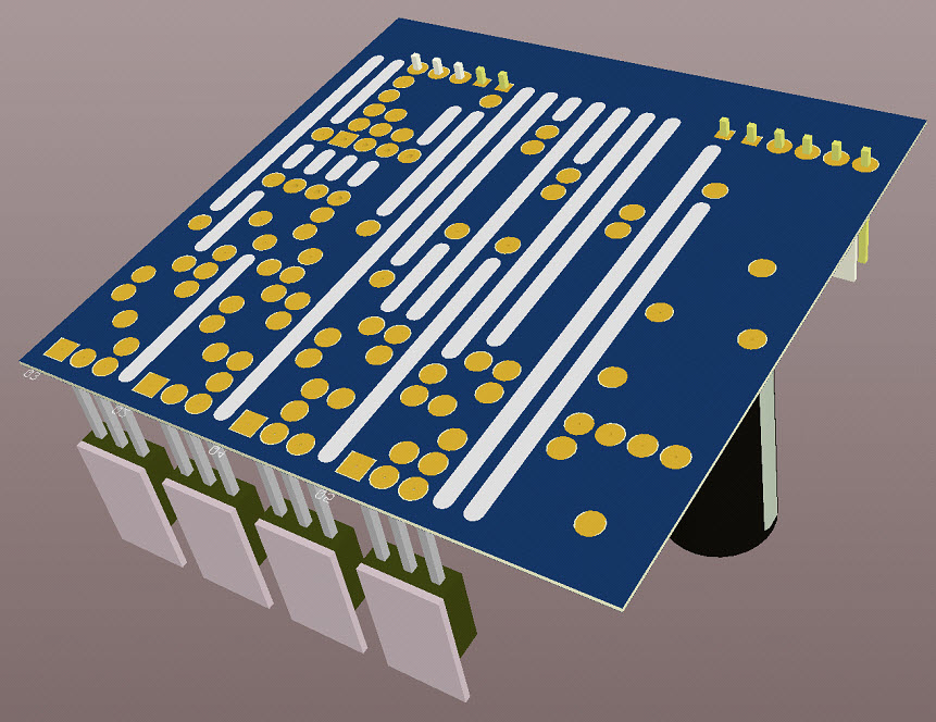
3D
top view
bottom view
PCB
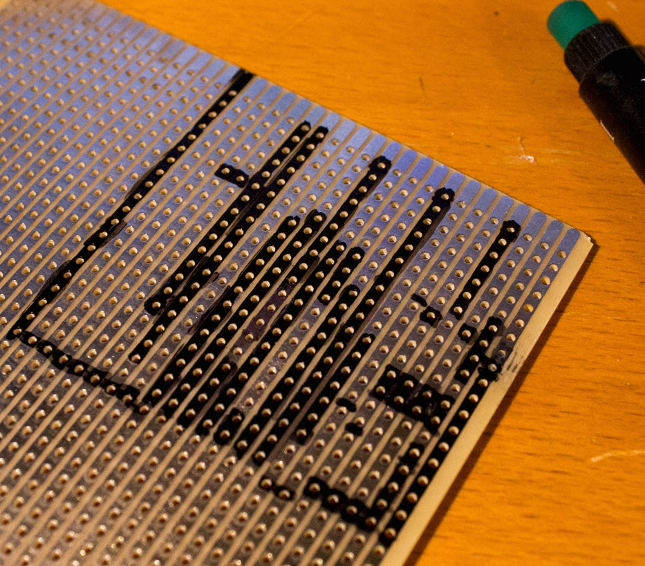
Blacked out for tracks that will be separated
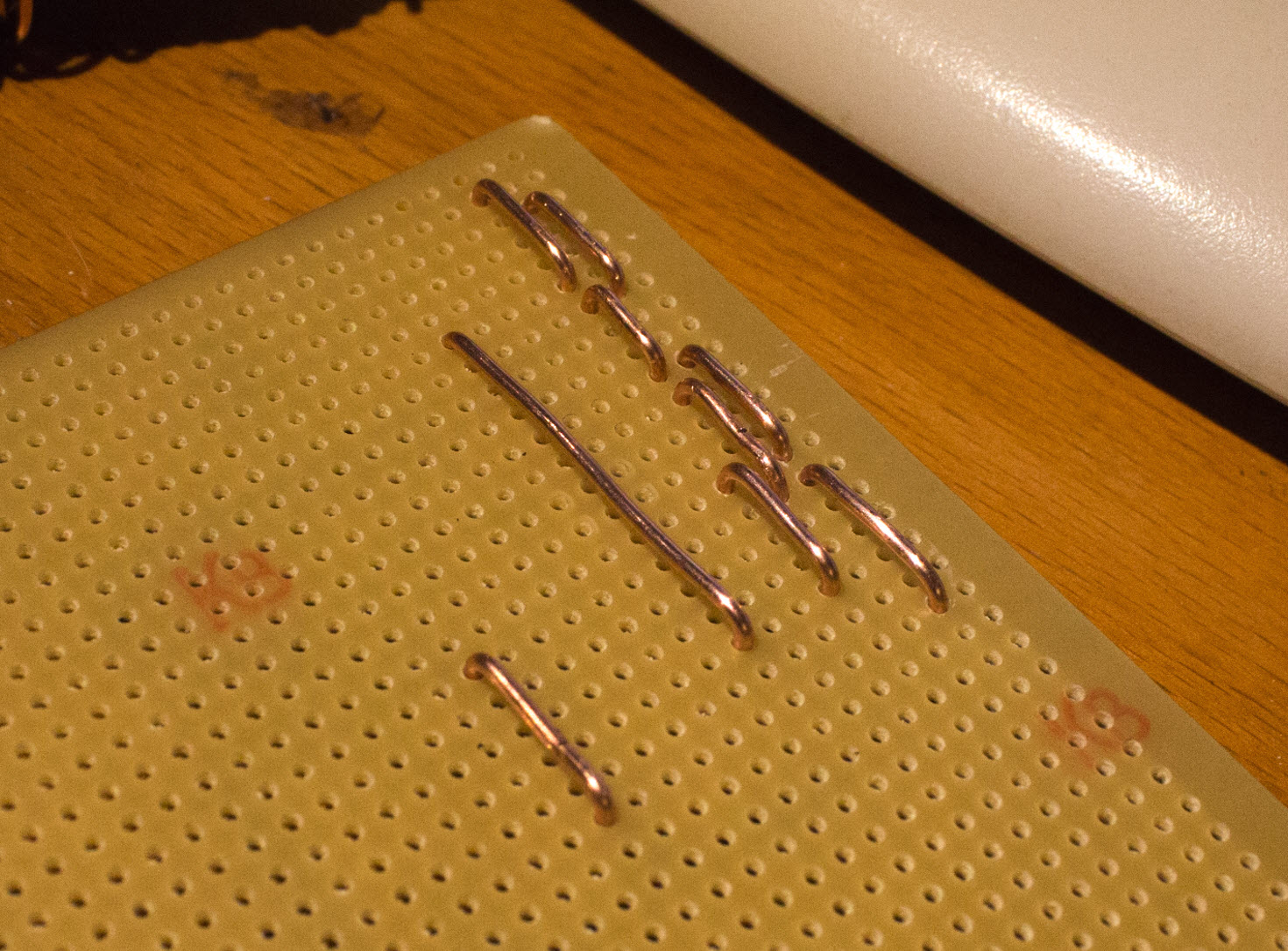
first copper wires that supplies higher current
solid 1.75mm²
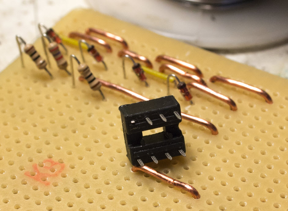
Cut one leg.
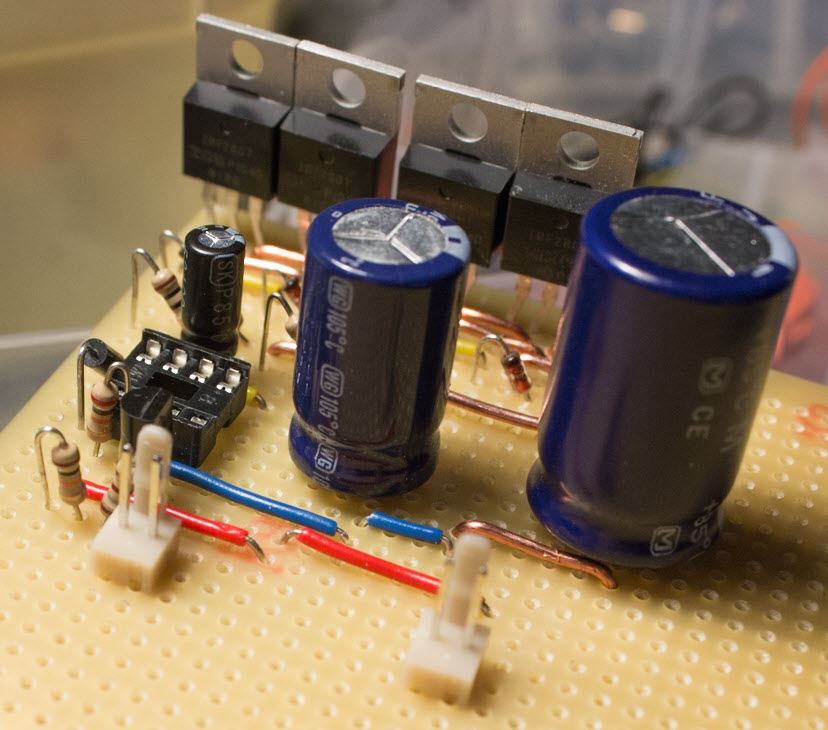
Placing components
Various resistors and zener diodes
one leg is NC for the IR2111
PWM PCB on the way
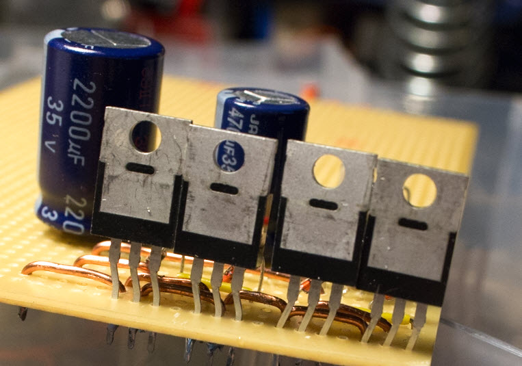
A tiny spacing error
-not a problem as long as upper and lower mosfet do not touch
Power wires
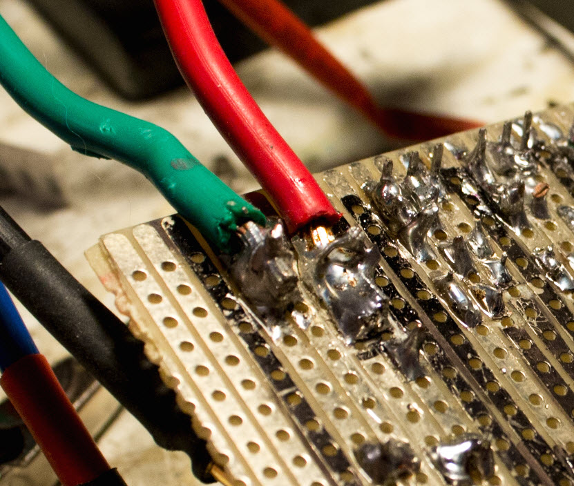
Eylets through pcb to retain wires
Enclosure
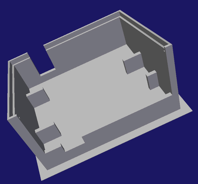
lower part of enclosure
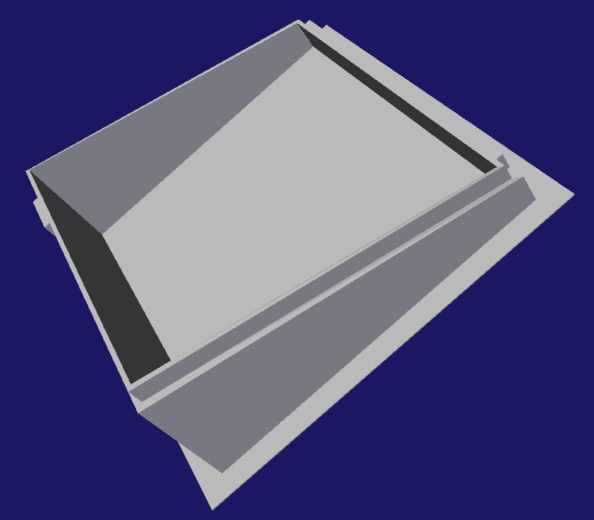
PWM box lid
Managing heat dissipation
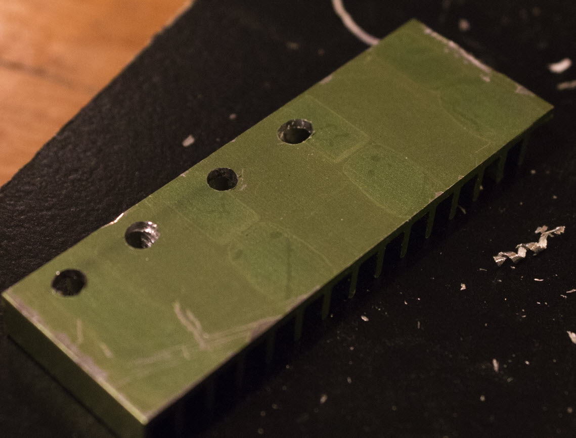
Old motherboard VRM cooler
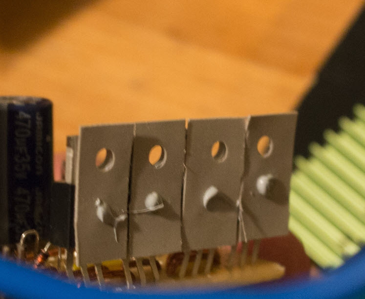
Bead of thermal paste
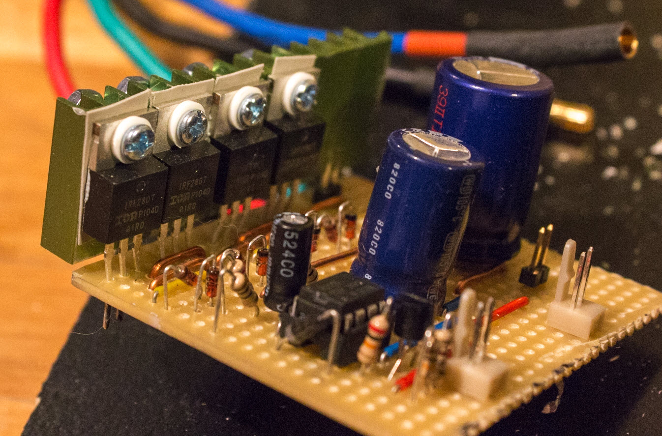
Isolation pads and compund
Arduino and I/O ports
layout
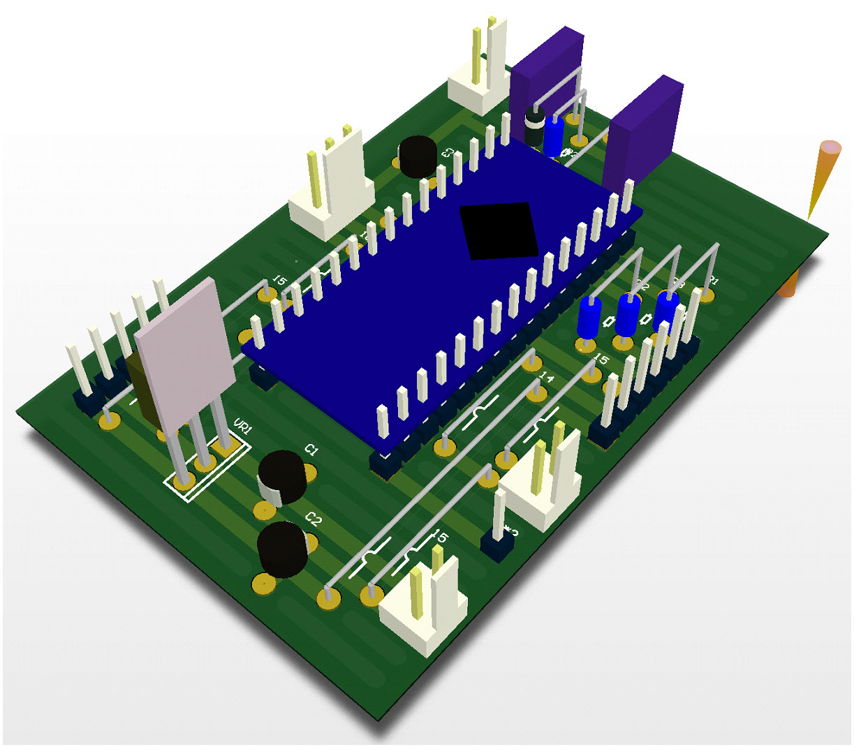
Top view
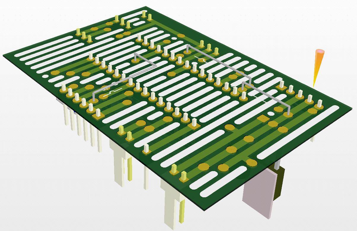
Bottom view
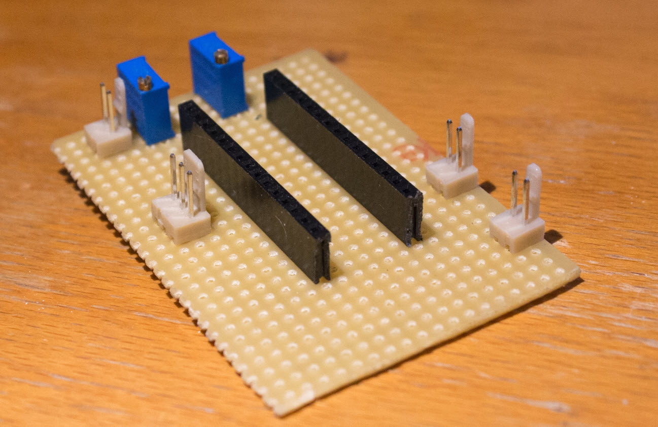
Begin placeing components

Botto
Code
C-File
H-file I2C
H-file Liquidcrystal
Youtube
Spme test runs
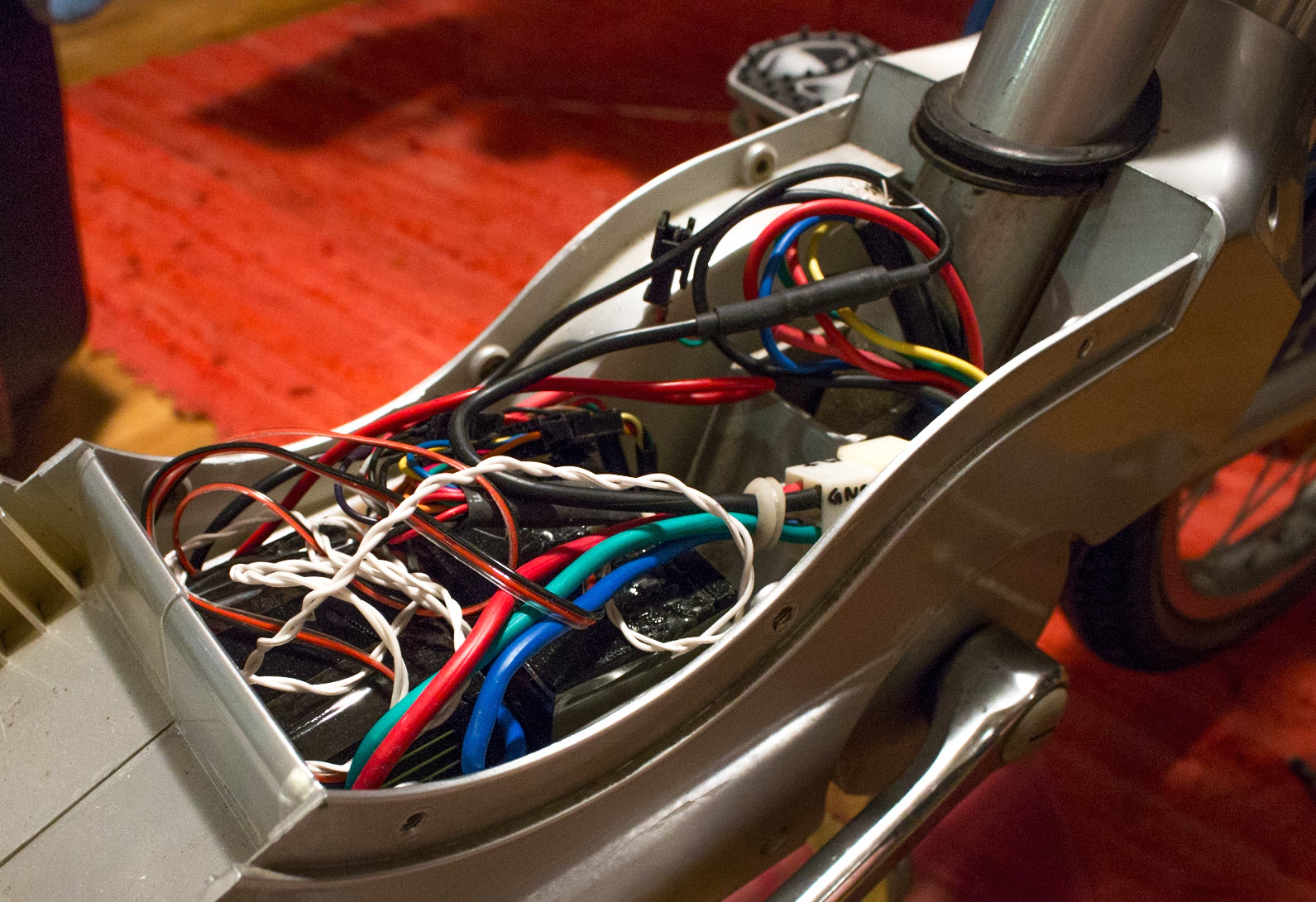
All wires packed in
